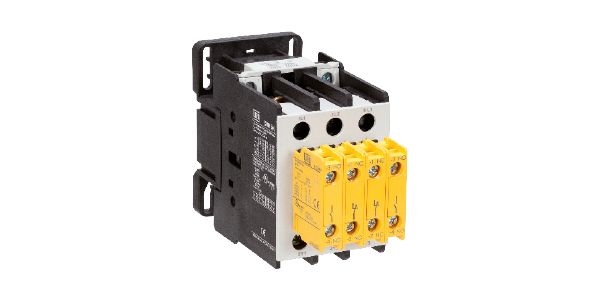


Applicable to the auxiliary contacts used in command auxiliary circuits. Those contacts can be integrated to the contactor or in blocks of external contacts mechanically linked to the contactors.
According to IEC 60947-5-1 - Annex L, open contacts and closed contacts cannot be simultaneously closed. In case welding occurs on the NO contacts, the NC contacts must remain open, and in case welding occurs on the NC contacts, the NO auxiliary contacts must remain open. Contactors with those characteristics are often used in self-monitoring circuits combined with safety interfaces (e.g., safety relays) used in the automation and safety of machinery and equipment.
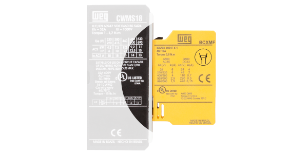
Side indication of the symbol of mechanically linked contacts.


Applicable to the auxiliary contacts mechanically linked to the power contacts.
NC auxiliary contacts cannot be in the closed position at the same time as the power contacts will are open when the contactor coil is energized.
These auxiliary contacts are called mirror contacts in order to prevent confusions with the term "mechanically linked" used by IEC 6094-5-1- Annex L; however, these auxiliary contacts may meet the two requirements, both IEC 6094-4-1 - Annex F and IEC 60947-5-1 - Annex L.
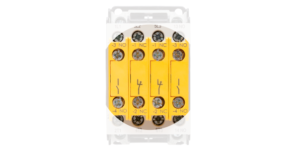
Front marking of the symbol of mirror contacts.